Introduction
Diagnostic techniques are very much linked to the use of test equipment. In other words, you must be able to interpret the results of tests. In most cases, this involves comparing the result of a test to the reading given in a data book or other source of information. By way of an introduction, Table 3.1 lists some of the basic words and descriptions relating to tools and equipment.
Basic hand tools
You cannot learn to use tools from a book, it is clearly a very practical skill. However, you can fol[1]low the recommendations made here and, of course, by the manufacturers. One thing to highlight, as an example, is the number of different types of screwdriver ends, as shown in Figure 3.2. These are worthy of mention because often using the wrong driver and damaging the screw head causes a lot of trouble.
Accuracy of test equipment
Consider measuring the length of wire with a steel rule. How accurately could you measure it? To the nearest 0.5 mm? This raises a number of issues: first, you could make an error reading the ruler. Secondly, why do we need to know the length of a bit of wire to the nearest 0.5 mm? Thirdly, the ruler may have stretched or expanded, and so does not give the correct reading.
The first and second of these issues can be dispensed with by knowing how to read the test equipment correctly and also knowing the appropriate level of accuracy required. A micrometer for a plug gap? A ruler for valve clearances? I think you get the idea. The accuracy of the equipment itself is another issue.
Basic test meters
An essential tool for working on vehicle electrical and electronic systems is a good digital multimeter. Digital meters are most suitable for the accuracy of reading as well as their available facilities. The list of functions given in Table 3.3, which is broadly in order, starting from essential to desirable, should be considered
A way of determining the quality of a meter as well as by the facilities provided is to consider the following:
- Accuracy,
- Loading effect of the meter,
- Protection circuits.
How to use a millimeter
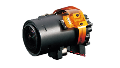
A crankshaft or camshaft (phase) sensor can be tested in a number of ways. Resistance (inductive type), AC output voltage or the signal frequency can be measured. The method shown here is a measurement of frequency, about 34.7 Hz at the cam or phase sensor
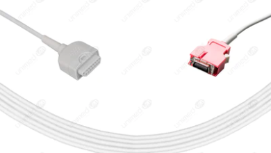
To test an oxygen sensor (lambda sensor) set the meter to DC volts and note the maximum and minimum figures. Some meters will record this automatically. A reading that varies between about 0.2 V and 0.8 V usually indicates correct operation. Note that some sensors have a heater element, which is supplied with 12 V
To measure current the circuit must either be broken and remade with the meter or an ‘inductive’ clamp used. In this case, a clamp is used showing the current flowing into the battery from the alternator. Note that the meter for these tests is often set to mV and that the sensitivity varies.
Last word
Testing RPM involves either connecting to the coil negative terminal or using a clamp on a plug lead. In this case the test is being carried out on a distributor less ignition system, which because of the lost spark and no distributor means the reading should be doubled.